Interactive Devices
Creative Embedded Systems Project 2
The Assignment:
The goal is to create an interactive device with the following hardware: ESP32 TTGO T-display, a button, a joystick and a potentiometer. The devices will connect to your computer and send data back to your laptop for visualization, sonfication, or whatever media generation process you prefer.
From a hardware perspective, you will need to connect the specified components to the ESP32 and create an enclosure for the device. From a software perspective, you will write an ESP32 program that collects sensor data and sends it over either a serial or wifi connection to a laptop. You will also write a media generation program on your laptop to handle this data and create something interesting with it.
My Project:
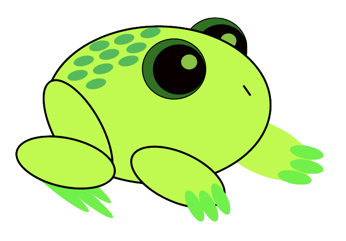
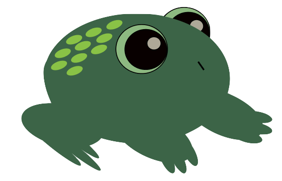
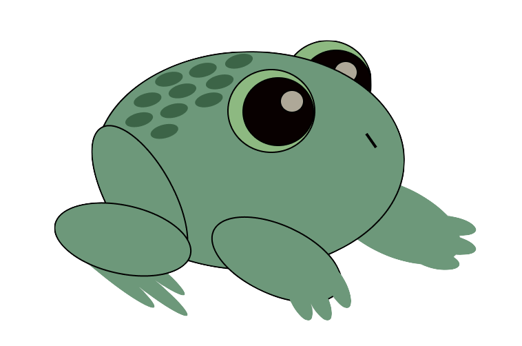
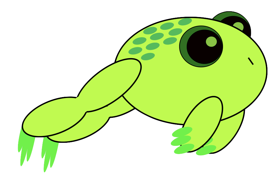
For this assignment, I wanted to have my hardware interact with a website that was leaning more towards an art project than a coding assignment that I would get as homework from one of my classes. I decided to brainstorm some ideas and doodle a bit and I landed on creating an interactive background or “scenic view” and some sort of plant or animal that can move around the screen. These aspects would be controlled by the potentiometer and the joystick (respectively). Since my background was going to be changeable, I liked the idea that my organism would be able to change as well. Additionally, I needed a way to incorporate the button. Therefore, I started thinking about animals that go through metamorphosis and decided on drawing the stages of a frog’s lifecycle. I was able to bring in my artistic side this way as well by drawing my own versions of the different stages leading upto a frog, and adding my png’s to the project. To create this I followed the steps below.
General Steps
- Connecting the button
- Connecting the potentiometer
- Connecting the joystick
- Building an enclosure
- Writing the software
Hardware Setup:
In order to know where to connect things, we will revisit the pinout diagram of the board we are using. This tells us what each pin can do.
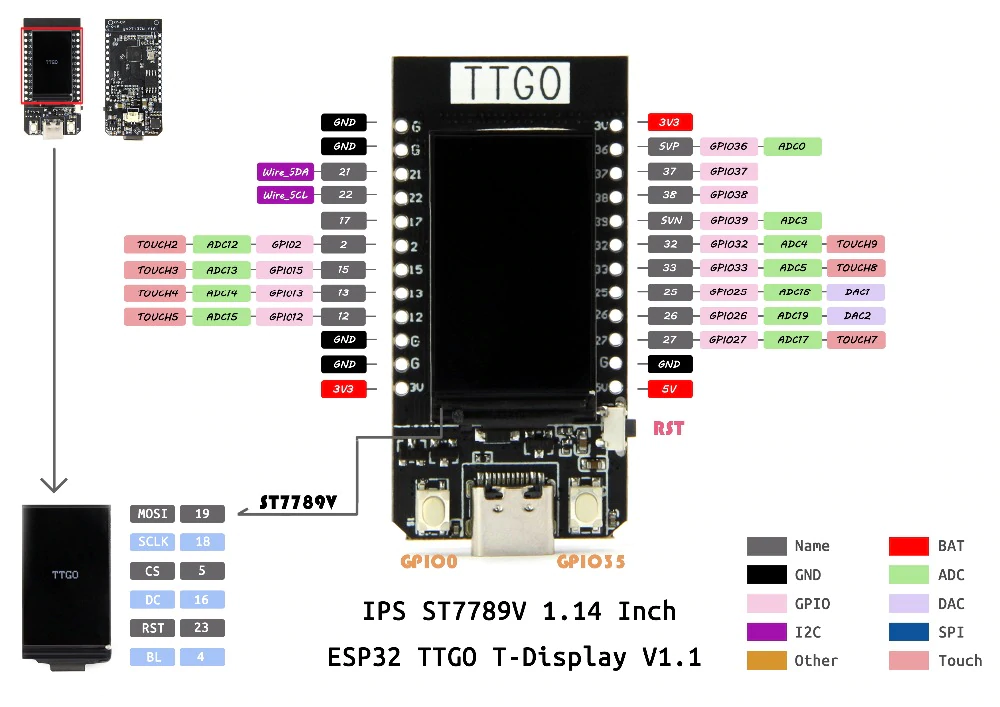
I connected my ESP32 to a breadboard and used female-female and male-male wires to connect the sensors to the correct spots in the board. For the button, one wire went to G and another went to pin 22. For the potentiometer, the middle pin/wire went to pin 15 and the outer two went to G and 3.3V. Finally, for the joystick the pin that says GND goes to G, the pin that says 5V goes to 3V, the pin that says VRx goes to pin 12 and the pin that says VRy goes to pin 13.
Software Setup:
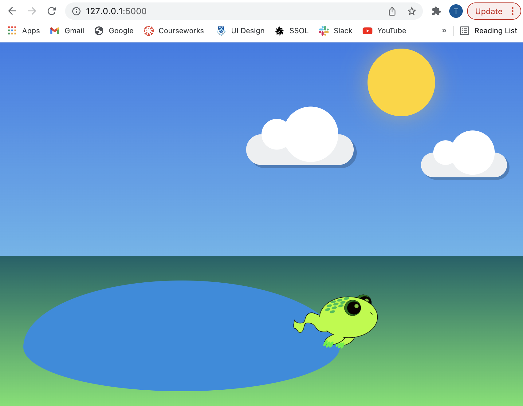
I wrote two programs for the software: one arduino .ino program and a web application (using flask). The .ino program should be uploaded to the ESP32 and sends the sensor data through the serial connection to the computer. To run the website, go to the directory with the server.py file, run it (python3 server.py), then go to the url indicated in your terminal. The web application (specifically the .js file) accesses the serialized sensor data and the website reacts accordingly.
An important library I used for packaging the sensor data as a JSON object is: ArduinoJson.h
- helpful link: https://arduinojson.org/
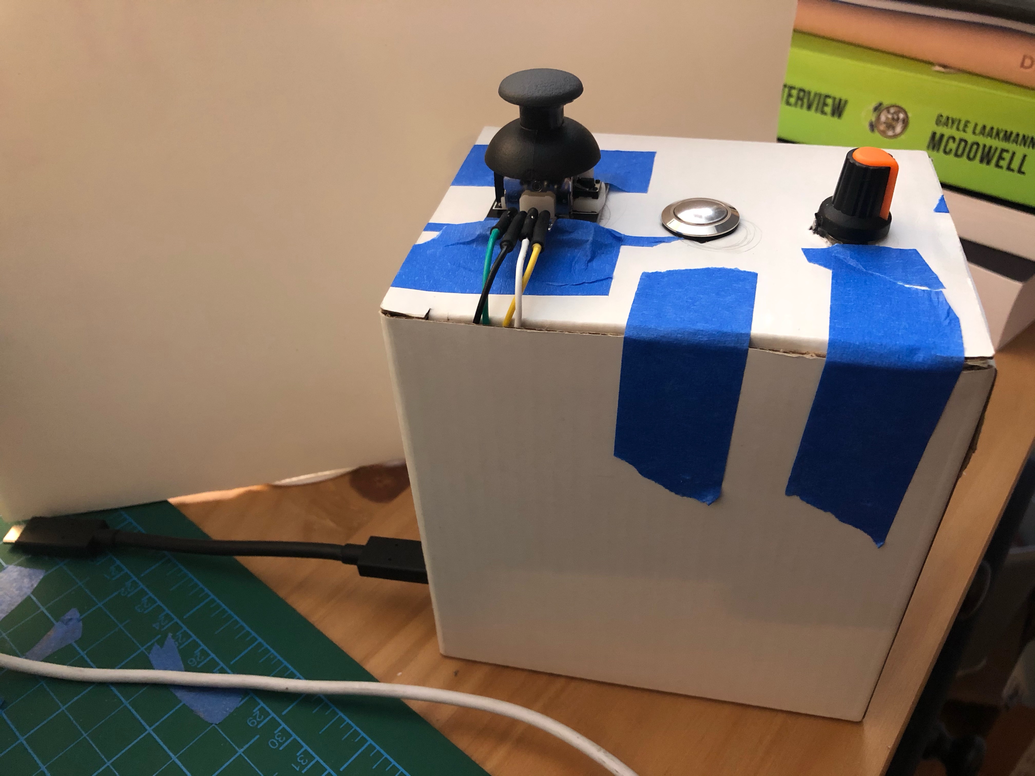
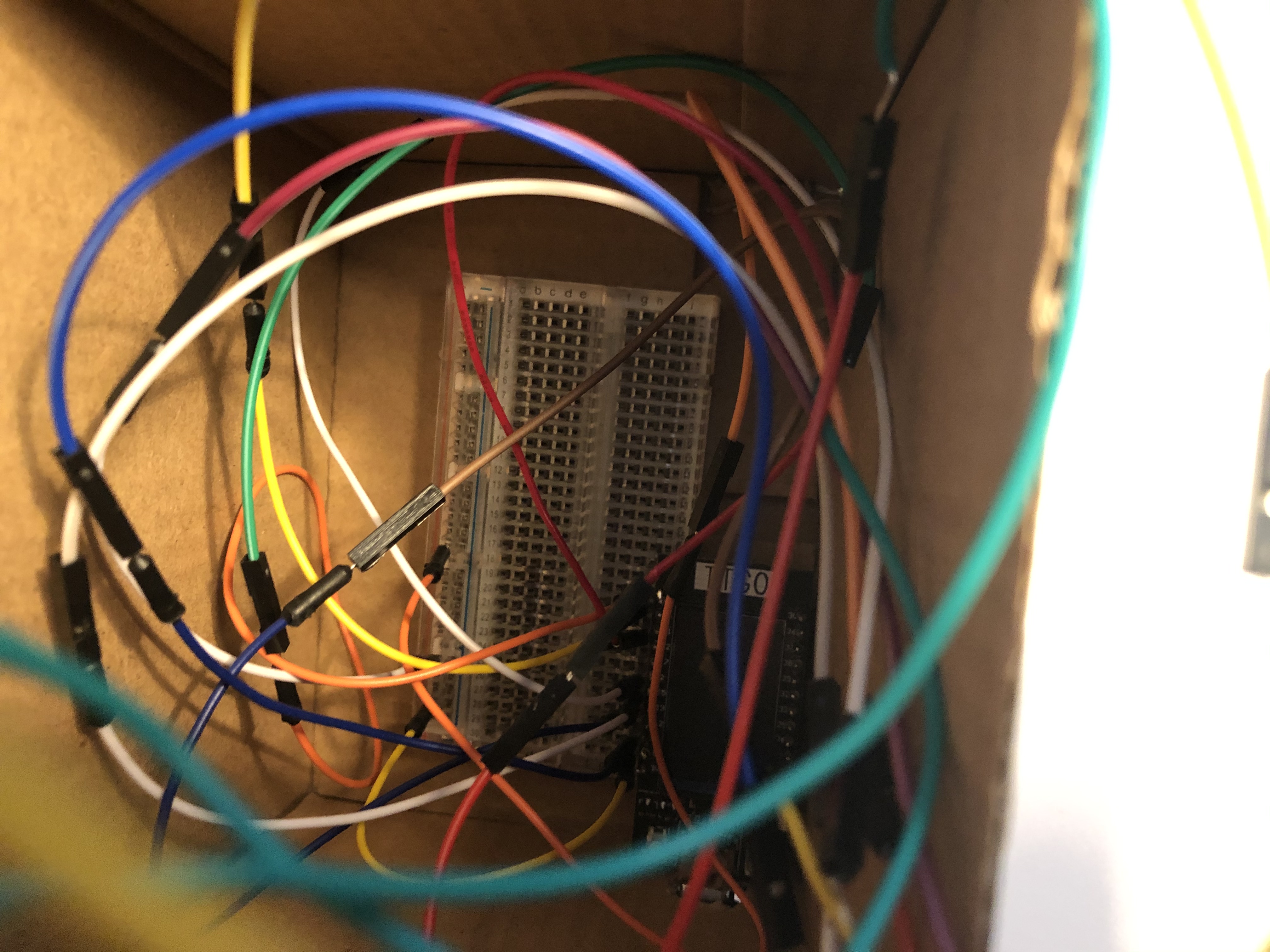
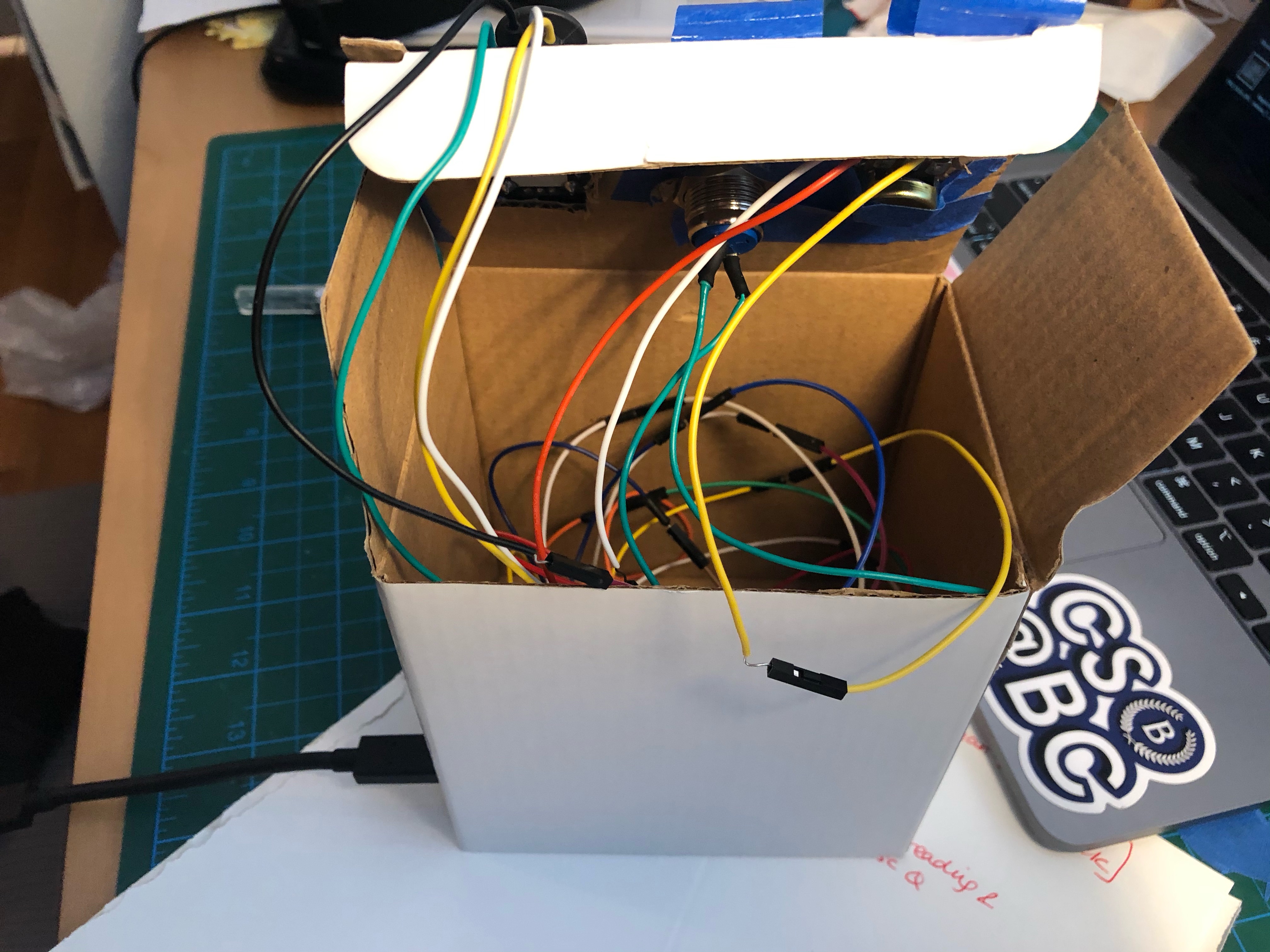
Container Setup:
I took a small cardboard box and cut holes at the top for the 3 sensors and one for the USB cable. I secured the breadboard to the bottom of the box and connected all the wires correctly.
Get it going!
If embedding doesn’t work, here’s the link to the youtube video: https://youtu.be/tnW0U-qQn9Q